
Connecting LoRa Devices to Kaa IoT Platform: An In-Depth Tutorial
In this tutorial, we'll walk you through the process of connecting LoRa devices to the Kaa IoT Platform. Kaa IoT Platform is a flexible cloud IoT platform for device management and data analysis. Unlock the potential of IoT now by signing up for a free 14-day trial of Kaa IoT Platform!
But before we delve into the practical steps, let's begin with a foundational understanding of the technology. First, we'll discuss the differences between LoRa, LPWAN, and LoRaWAN, explaining each of them. Next, we'll discuss LoRaWAN in greater detail, mentioning its pros and cons.
LoRa vs. Modbus Sensors: What to Choose for Your IoT Solution?
LoRa basics
LoRa stands for Long Range, a wireless modulation method derived from Chirp Spread Spectrum (CSS) technology. It works by encoding information onto radio waves through chirp pulses. Semtech developed LoRa to standardize low-power, wide-area networks (LPWANs).
More extensive than Wi-Fi, Bluetooth, or ZigBee networks, its high range is a major selling point. In a city, LoRa can transmit up to five kilometers, which is about three miles. However, in rural areas with a clear view, its range can increase to more than 10 miles (15 kilometers).
Low power requirements are a key feature of LoRa-based solutions. Due to their reduced power requirements, battery devices can now operate on a single battery for an astounding 10 years. These IoT devices typically gather small amounts of data. When set up in a star topology, a network based on the open LoRaWAN protocol is ideal for use cases that require extensive in-building or long-distance communication between devices.
What is LPWAN (Low Power Wide Area Network)?
LPWAN is a slow but long-range wireless network that is great for connecting IoT devices. It's a type of wireless network that can connect devices over long distances while using very little power. LPWANs are different from traditional wireless networks, which are designed to carry large amounts of data quickly.
Some examples of LPWAN technologies include LoRa/LoRaWAN, Sigfox, MIoTy, Wi-SUN, LTE-M, and NB-IOT.
What is LoRaWAN?
One of the most important players in the LPWAN field, LoRaWAN is a protocol for the Media Access Control (MAC) layer of LPWANs that uses the LoRa radio modulation method. Its primary role is to establish wireless connectivity for devices, enabling them to link to the Internet, all while efficiently managing communication between end-node devices and network gateways.

Let's delve into some of LoRaWAN's more practical uses to learn more about this technology.
LoRaWAN use cases
- Vaccine supply chain integrity. LoRaWAN sensors play a vital role in preserving the integrity of vaccine supply chains and ensuring that vaccines remain within the appropriate temperature range during transportation.
- Wildlife conservation efforts. LoRaWAN tracking sensors are employed to safeguard endangered species, such as the Black Rhinos and Amur Leopards, by monitoring their movements and habitats.
- Enhanced care for dementia patients. Wristband sensors equipped with fall detection and medication tracking capabilities provide essential support for dementia patients, enhancing their safety and well-being.
- Sustainable agriculture through smart farms. Real-time data insights on crop soil moisture levels enable optimized irrigation schedules, leading to a significant reduction in water consumption of up to 30%.
- Water network maintenance and conservation. LoRaWAN technology aids in the early identification and prompt repair of leaks within a city's water network, contributing to water conservation efforts.
- Food safety assurance. Temperature monitoring solutions powered by LoRaWAN technology ensure the consistent maintenance of food quality throughout the supply chain.
- Efficient waste management with smart bins. Smart waste bins equipped with level sensors alert staff to optimize waste pickup schedules, reducing unnecessary trips and improving efficiency.
- Remote bike tracking. LoRaWAN-based bike trackers are deployed in remote areas and densely populated buildings to track the location and status of bikes, enhancing bike security and management.
- Airport operations optimization. GPS-free tracking solutions utilizing LoRaWAN technology provide real-time monitoring of vehicles, personnel, and luggage within airports, streamlining operations and enhancing security.
- Smart workspaces for enhanced productivity. LoRaWAN sensors monitor room occupancy, temperature, energy usage, and parking availability, allowing for the optimization of workspace environments and resource utilization.
- Livestock health management. Sensors powered by LoRaWAN technology enable the continuous monitoring of cattle health, early disease detection, and forecasting of calving times, ensuring the well-being of livestock.
How does LoRaWAN work?
LoRaWAN networks employ a star-of-stars topology, as illustrated in the diagram below.

A standard LoRaWAN network comprises the following key components:
- End devices. A LoRaWAN device is a sensor and/or actuator that sends LoRa-modulated wireless messages to gateways or receives wireless messages from them. These end devices establish their wireless connection with the LoRaWAN network through gateways, utilizing the LoRa RF modulation technique.
- Gateways. LoRa gateways receive messages from end devices and forward them to the Network server. Each LoRa gateway is registered with a LoRaWAN network server through specific configuration settings. In order to communicate with the network server, gateways need backhaul connections, such as cellular (3G/4G/5G), WiFi, Ethernet, fiber optic, or 2.4 GHz radio links.
- Network server. The network server is a piece of software hosted on a server that oversees the entire network, managing gateways, end devices, applications, and users.
- Application server. Application servers handle application-specific data messages coming from end devices. Additionally, they generate application-layer downlink payloads and transmit them to connected end devices through the network server. It's worth noting that a LoRaWAN network can have multiple application servers for various applications and use cases.
- Join server. It’s a piece of software running on a server that processes join-request messages sent by end devices. The join server assists in secure device activation, root key storage, and session key generation.
End devices in LoRaWAN networks connect with neighboring gateways, and the gateways in turn connect to the network server. LoRaWAN networks rely on the ALOHA-based protocol, eliminating the need for end devices to establish direct connections with specific LoRa gateways.
Whenever the LoRaWAN sensor sends a message, it is broadcasted to all nearby gateways. The network server then receives these messages. Network servers perform message deduplication when they receive multiple copies of the same message and only keep the original.
LoRaWAN advantages
- Ultra-low power. LoRaWAN end devices are finely tuned for low-power operation, boasting the ability to function for up to a decade on a single coin-cell battery.
- Long range. LoRaWAN gateways are able to send and receive signals across significant distances.
- Deep indoor coverage. LoRaWAN networks provide extensive indoor coverage and easily reach all levels of a building.
- No licensing fees. Deploying a LoRaWAN network does not entail costly frequency spectrum license fees.
- Geolocation. Leveraging triangulation techniques, a LoRaWAN network can ascertain the location of end devices without GPS. At least three gateways are required to pick up the signal of a LoRa end device for accurate positioning.
- Robust security. LoRaWAN ensures secure communication between end devices and application servers by employing AES-128 encryption.
- Over-the-air firmware updates. You can remotely update the firmware of individual end devices or a group of them, including both applications and the LoRaWAN stack.
- Seamless roaming. LoRaWAN end devices can smoothly transition from one network to another, enhancing their versatility.
- Cost-effectiveness. LoRaWAN networks are cost-effective due to minimal infrastructure requirements, budget-friendly end nodes, and the availability of open-source software.
LoRaWAN disadvantages
- Limited throughput. The data transmission speed in LoRaWAN networks can be relatively slow, with throughput varying depending on the specific physical layer technology used. Speeds can range from several hundred bits per second to several tens of kilobits per second.
- Data transmission delay. Some delay in data transmission occurs from the moment a sensor sends data to when it reaches the end application. The delay duration can vary from a few seconds to several tens of seconds.
- Spectrum noise risks. Operating within an unlicensed frequency range exposes LoRaWAN to the potential for interference from other devices, leading to spectrum noise.
- Proprietary modulation technology. The LoRa modulation technology is proprietary and protected by Semtech patents.
- Signal power constraints. LoRaWAN networks may face limitations on signal power, affecting their overall reach and coverage.
For more in-depth technical information, you can refer to the LoRa Developer Portal.
Now, with a solid grasp of the foundational concepts of LoRa and LoRaWAN, we'll embark on a detailed tutorial to help you connect your LoRa devices to the Kaa IoT platform, step by step.
Connecting LoRaWAN devices to the Kaa IoT platform
In order to connect a LoRaWAN device to the Kaa IoT platform, at least two elements are required:
- LoRaWAN gateway
- LoRaWAN network server
We use ABP (Authentication by Personalization) mode to keep things simple. This will allow us to use only the network server, but not a join server, because there will be no registration procedure. Session keys (AppSKey & NwkSKey) will be prescribed in advance on the device and network server.
The task of the gateway is to provide, on the one hand, a wireless communication channel using LoRa technology and, on the other hand, data transmission through the computer network to the network server.
The task of the network in our case is to receive packets from the gateway and decrypt them using NwkSKey.
In order to simplify the architecture in our case, the network server will have the ability to decrypt and payload using AppSKey. Thus, at the output of the network server, we will have complete data ready for further processing (if necessary) and sending to the Kaa IoT platform.
- As a LoRaWAN gateway, we chose Dragino LPS8 for the band 868MHz;
- As a simple network server, we chose Node-RED nodes: node-red-LoRa;
- As a LoRa device, we chose the Water Leak sensor SL200EU. SL200 water leak sensor is based on standard LoRaWAN Class A. We selected the sensor for the band 868 MHz.
Note: The sensor and gateway must operate in the same frequency band that is authorized for use in your region. For more details on LoRaWAN usage in your region, please refer to the RP002-1.0.4 Regional Parameters document.
Sensor configuration
Before the sensor connection, we need to install a USB-to-Serial Driver (and the version for Windows 11 is here).
To configure the sensor, we need the Sensor Tool utility. Various versions of this utility are available here. We need to download and install the 1.5.4 version from here. Detailed instructions for this utility can be found here.
When everything is downloaded and installed, follow the next steps:
- Connect the sensor to the laptop using a Type-C cable.
- Click “Refresh”.
- Choose the device and BaudRate is 115200, then “Open UART”.
Note: If the device is not connected or the serial port is not Other device, you can’t read the device information. Please check the DevEUI to make sure you connect the right device.
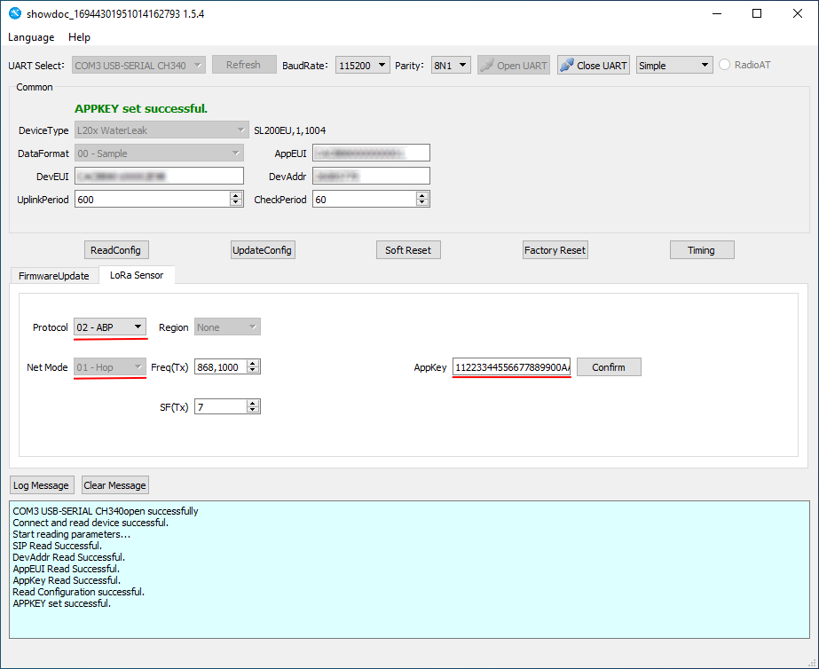
The next step is to click “ReadConfig” and we can see the current sensor configuration.
For clarity, we will not use the App Key that is listed on the sensor packaging, but rather the key 1122333344556677889900AABBCCDDEEFF.
Note: This key is used for demonstration purposes only. In a real-life situation, it is preferable to use the key indicated on the package or another unique key for security reasons.
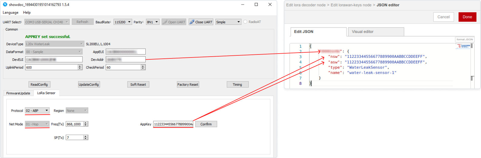
- Change the following settings (highlighted in red in the 3-point figure):
- Select ABP mode (since we don't want to use the Join procedure);
- Set NwkSKey and AppSKey.
Note: According to the manufacturer's documentation for this sensor for ABP mode "APPSKEY and NETSKEY are the same". That's why we only install AppKey.
- After entering the key, click “Confirm”.
Important: Remember or save somewhere: DevAddr. We will use this number when configuring the network server.
Sensor configuration is finished. Now click “UpdateConfig”. And we’re ready to configure the gateway, which is Dragino LPS8 in our case.
Dragino LPS8 Configuration
Connect the Ethernet cable from your Internet service provider or router to the gateway. After that, apply power to the gateway.
The LPS8 is configured as a WiFi Access Point by default. You can access and configure the LPS8 after connecting to its WiFi network or via its WAN Ethernet port.
Let's look at connecting via WiFi.
When the gateway boots up, a new WiFi network named "dragino-xxxxxxx" will appear. The password is "dragino+dragino".
You can use a PC to connect to this WiFi network. The PC will get an IP address of 10.130.1.xxx and the LPS8 has the default IP of 10.130.1.1.
Open a browser on the PC and type in the LPS8 IP address (depends on your connect method) http://10.130.1.1/ (Access via WiFi AP network).
The account details for web login are:
User Name: root
Password: dragino
You can find more information about the settings here.
We have successfully logged into the Gateway UI.
Radio Channel Check
First of all, let's make sure that we receive some data from the sensor. Before we do that, let's make a couple of test hits on the sensor so that it sends some data.
Go to LogRead / LoRa Log. In Logread RxTxJson we should see packets:
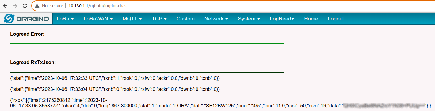
In the Logread REPORT, we should see some data as well:
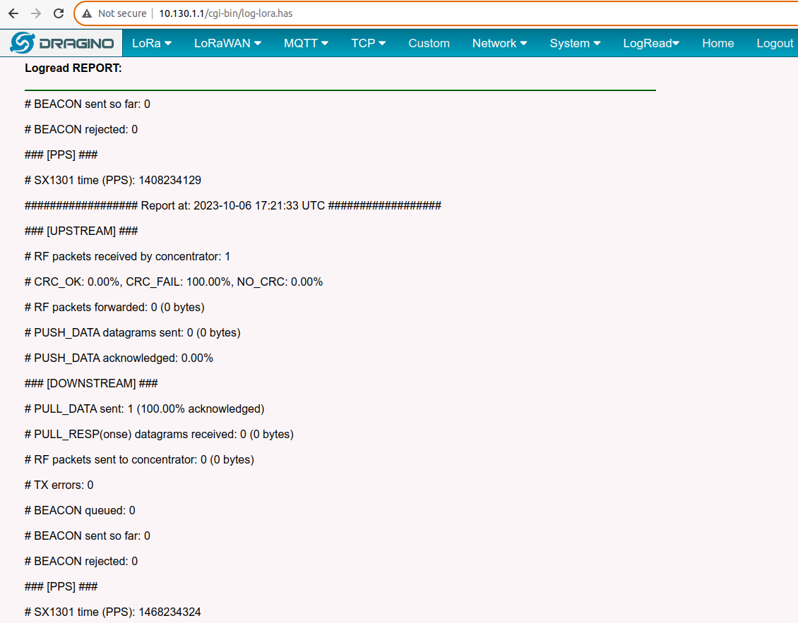
If no data is available, make sure the sensor and the gateway have the same frequency ranges, the sensor is properly configured, in good working order, and powered.
LoRaWAN Configuration
We need to configure the LoRaWAN configuration for the gateway, where we will select the desired packet forwarder and specify the network server.
In this case, we will use the Semtech UDP packet forwarder as a packet forwarder because of its simple implementation.
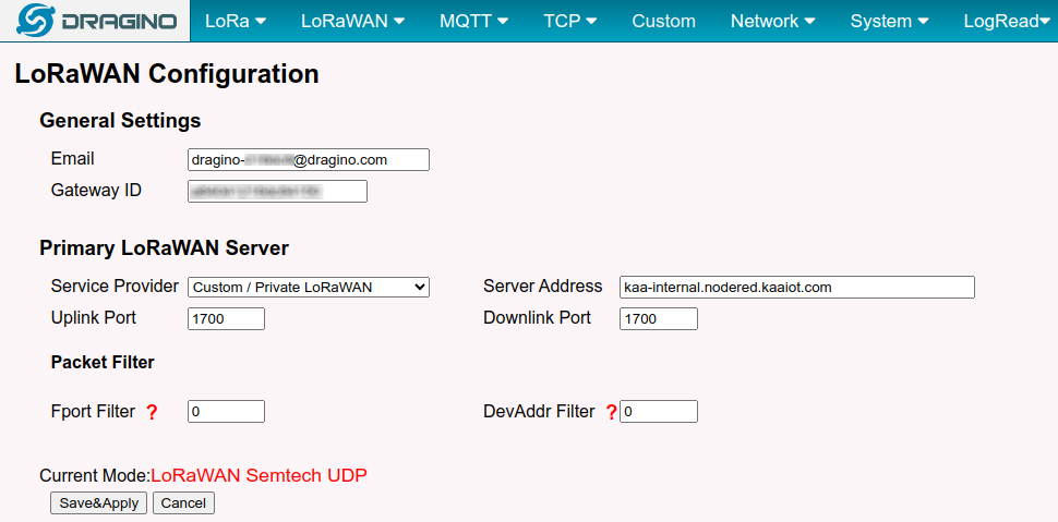
- Go to LoRaWAN / LoRaWAN - Semtech UDP. Here, we need to specify:
- Server Address: the address of our network server;
- Uplink Port and Downlink Port: ports of our network server.
-
Enter the Server Address. The network server will be Node-RED, so theserverr address will be
<tenant ID>.nodered.kaaiot.com
where <tenant ID> is your tenant ID. In our case, the Server Address will be kaa-internal.nodered.kaaiot.com. - Click Save&Apply to save the configuration.
The gateway configuration is completed, and now we can configure Node-RED.
Node-RED сonfiguration
Kaa Node-RED is now available directly as part of the Kaa IoT platform.
Network server
Here, we’ll use the Node-RED nodes called node-red-LoRa as our LoRaWAN server. We need to add them to our Node-RED. To do this, perform the following:
- Click on the drop-down menu in the upper right corner and go to Manage Palette.
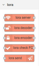
- Go to the Install tab and type @mschaeffler/node-red-LoRa into the search and click Install.

- The nodes will be installed, and you will see them in the list of nodes:
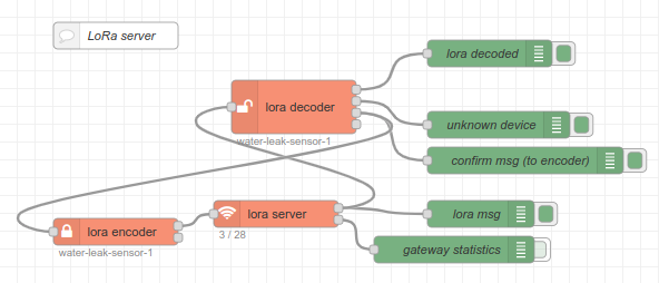
Now let's move on to creating our network server. - Let's create a new flow and name it LoRaWAN. Add our first node: the LoRa server and a couple of debug nodes. The UDP port of the LoRa server node should be 1700.
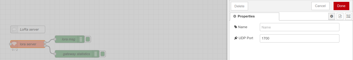
- Click “Deploy”.
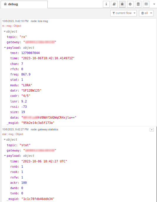
Now we can make a test response to the sensor to make sure that the data is coming. We can see that two messages appear in the debug window:
- The first message is the data packet;
- The second message is the statistics from the gateway.
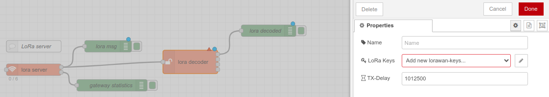
Now let's add a node to decrypt the received data using the LoRa decoder. For this node to work, we need to add the configuration of session keys. -
Go to the configuration of the LoRa decoder node, and in the LoRa Keys item, select Add new LoRawan-keys.
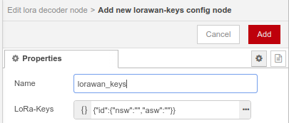
- Click on the three dots and enter the map deviceId | {NwkSKey, AppSKey}.
Remember: The key we used is 11223344556677889900AABBCCDDEEFF, and it’s the same for both NwkSKey and AppSKey. -
Enter the ID of our sensor (we wrote it down earlier when we configured the sensor) instead of the ID field and specify the encryption keys 11223344556677889900AABBCCDDEEFF in the values of the nsw & asw fields.
It’s also necessary to fill in the fields of type and name.
The type will be WaterLeakSensor, and as the name, we will use the token of the endpoint in the Kaa IoT platform (the process of registering the endpoint will be described later).
-
Click Done, Update, and Done. This completes the configuration of LoRa decoder.
Let's add a debug node to output 1 - this is where the data decoded with the help of our specified keys is received. When a packet arrives from the LoRa server, the LoRa decoder searches for session keys in the LoRawan_keys collection by deviceId. If a key is found, the data is decrypted and sent to output 1.
If there are no keys for the given deviceId, the packet goes to output 2.
If the message requires confirmation of reception, then output 3 receives a confirmation message, which will be sent to the encoder.
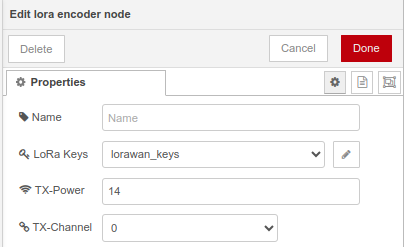
Note: It’s a must to configure access to encryption keys in the LoRa encoder (we need to select the storage created earlier). Here we can also configure TX-Power (transmit power for the gateway) and TX-Channel (transmit channel for the gateway).
- Click “Deploy”
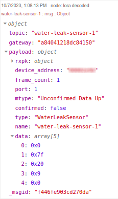
- Test the sensor and see the packet:
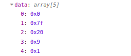
And when there is the presence of water:
We can see that in the topic, we have our endpoint token in the KaaIoT system. We can also see the decrypted data in the data field.
Let's check that this is what we expect according to the documentation.
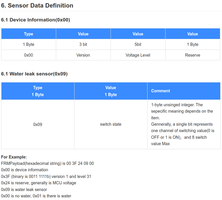
The 4th byte is 0x09, so the sensor type is correctly defined - Water leak sensor. The last byte is 0 or 1, depending on the presence or absence of water.
Data from the sensor is received and decoded. And now we can move on to the Node-RED configuration to send the data to the Kaa cloud.
Kaa IoT cloud account configuration
To connect your device to the platform, we first need to create an account and get a 14 days free trial.
Once the Kaa Cloud account is created and you are on the Kaa Cloud Web Dashboard, we need to create an application (let's call it “Water sensor”), application version , and endpoint.
If you face any issues, please read the “Connect your first device” tutorial. Also, we recommend reading the “Collecting data from a device” tutorial. This will provide a better understanding of how the platform accepts data from devices.
We created the application cjqb1umlt74c73codhm0 and endpoint with water-leak-sensor-1 token inside of this application:
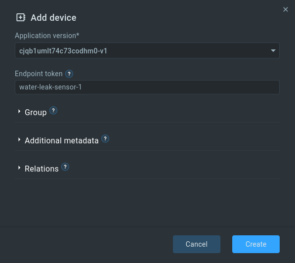
Note: Don't forget to enable the Autoextract option in the EPTS settings of your application and select Fallback strategy: server-timestamp (this will save time-series with the current server time in case the timestamp parameter is missing in the request).
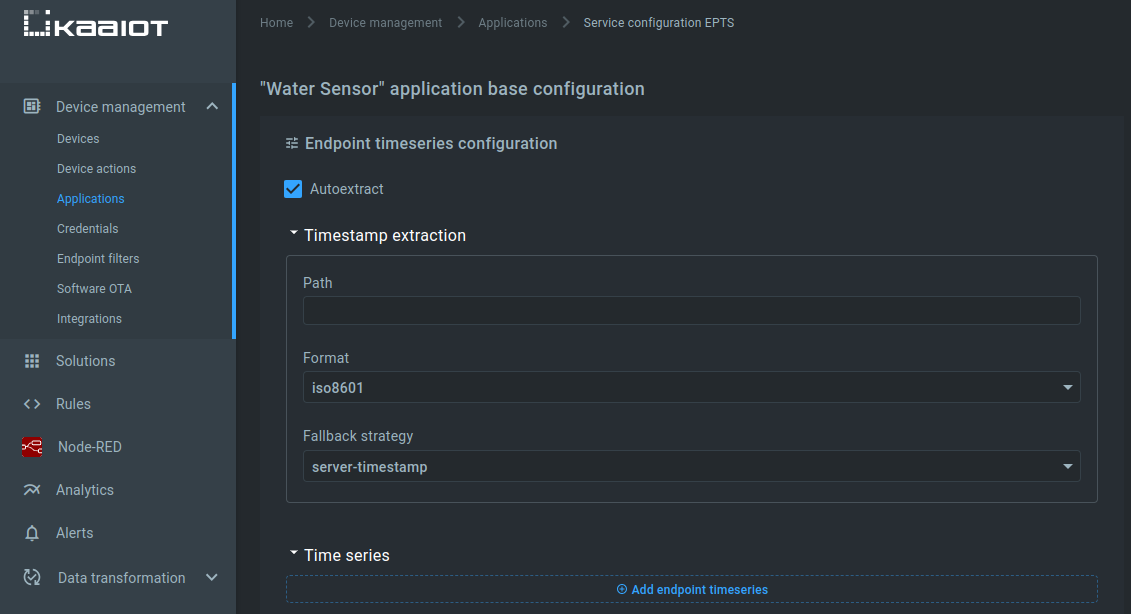
The same settings should be set for the application version.
Connection Node-RED to Kaa
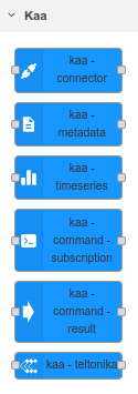
To make it easier to connect devices to the Kaa IoT platform, special nodes have been added to Node-RED:
We will send the current state of the sensor to time-series.
Note: The time series name has some limitations.
In order to send data to the time series of the platform, we need two nodes: kaa-timeseries and kaa-connector.
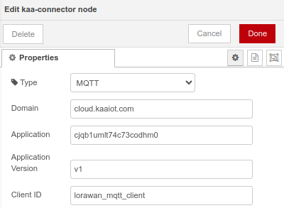
In the kaa-connector node, we need to configure a number of parameters:
- Type - connection protocol. Select MQTT. The use of MQTT protocol is preferable because in this case, it’s possible not only to get the latest data as quickly as possible, but also to react quickly and send control commands to the device, monitor its current status, connection;
- Domain - the domain where Kaa is hosted. If Kaa Cloud account is used, the domain will be cloud.kaaiot.com. In case of KaaIoT-hosted or Self-hosted you need to specify your domain;
- Application - here you should specify the application in which we created endpoint cjqb1umlt74c73codhm0;
- Application Version - specify the version of our application (for us it is v1);
- Client ID - ID of a client.
Configuration of nodes for sending time-series to the Kaa IoT platform is finished.
Now we need to convert the data received from the sensor into a form suitable for sending to the Kaa IoT platform.
The message coming to the input of the kaa-timeseries node for sending to Kaa should have the following form:
        msg.token = "endpoint-token";
        msg.payload = {
            "time-series-name": 12.0
        };
Reminder: From the output of the lora decoder, we receive data about the sensor state as an array. The token is also present in the topic parameter.
Let's create a node that converts the data from the sensor into a form suitable for sending to Kaa:
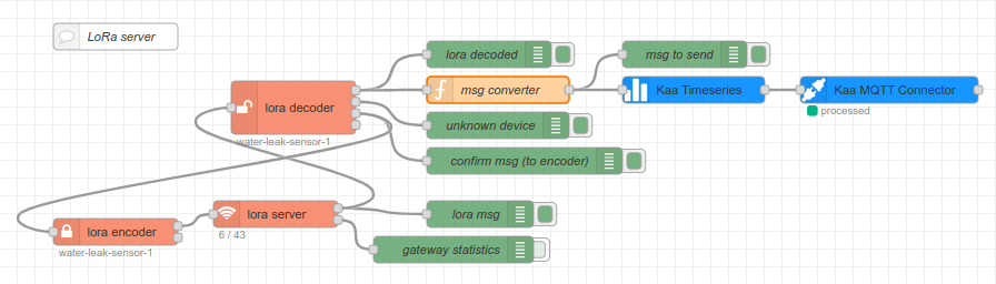
Internally, our msg converter node will contain the following code:
        let msgToSend = {};
        msgToSend.token = msg.topic;
        let sensorState = msg.payload.data[4];
        msgToSend.payload = {
            "state": sensorState
        };
        return msgToSend;
As you can see, we are creating a new object to send, adding a token to it and a payload that contains an object with the sensor state.
Let's click Deploy.
After that, we will do some test runs on the sensor and look at the msg to send:
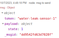
Just what we need!
Now Go to our endpoint in Kaa Cloud and see if the data appears there.
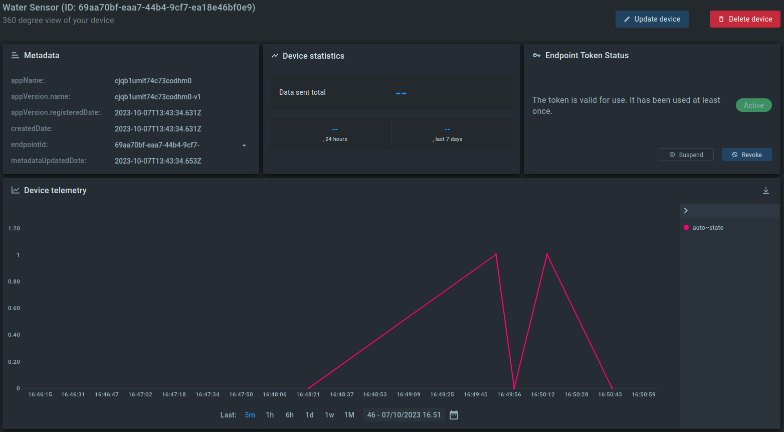
We can see that data has started to appear. The LoRaWAN leak sensor SL200 is now connected to the Kaa IoT platform.
Related Stories
KaaIoT and ELSYS join forces to bring robust smart building solutions with real-time climate monitoring.
Exciting news! KaaIoT has teamed up with Roomsys to promote smart building management IoT solutions!
The KaaIoT and Sensative partnership tackles a common challenge: water & oil leaks.
Seeed offers a wide range of IoT hardware products. This article explores how KaaIoT and Seeed are joining...