
Connecting Modbus Devices to Kaa IoT Platform: An In-Depth Tutorial
IoT protocols come in many forms, but Modbus is one of the most popular ones. Both IoT experts and enthusiasts use Modbus, a straightforward yet effective protocol, to connect a wide range of devices to the Internet. It finds widespread use in IoT applications ranging from factory automation to smart home tech.
LoRa vs. Modbus Sensors: What to Choose for Your IoT Solution?

In this tutorial, we will show you how to connect a Modbus device to the Kaa IoT platform. Kaa IoT platform is a cloud-based IoT platform that provides a wide range of features for managing and connecting IoT devices. By connecting your Modbus device to Kaa IoT platform, you get:
- Centralized management of your IoT devices.
- Secure data collection and storage.
- Real-time monitoring and alerting.
- Remote device control and configuration.
- Easy integration with other IoT devices and applications.
But first, let’s dig into what Modbus is, with its technical details.
What is Modbus?
The Modbus communication protocol stands as the granddaddy in the world of networking technologies. Over time, Modbus has not only endured but has also maintained its relevance in various applications spanning industrial automation, process control, building automation, transportation, energy management, and remote monitoring.
Virtually every sensor and controller device category has embraced Modbus networking, making it an omnipresent technology. From programmable logic controllers (PLCs), process controllers, and process instruments to sensors for monitoring processes and PID controllers, Modbus finds its way into motor drives, energy meters, SCADA systems (Supervisory Control and Data Acquisition), programmable automation controllers (PACs), discrete sensors, valves, and a myriad of other embedded devices.
Initially intended for communication between programmable logic controllers (PLCs) and computers, Modbus has since evolved into a standard communication protocol, seamlessly connecting diverse industrial electronic devices.
Modbus: Technical details
Modbus transport layers
RS-232, RS-485, and Ethernet are a few common transport layers used by the Modbus protocol, each of which is tailored to meet particular needs. Sometimes, RS-422 is used as well. While alternative options exist, these are the most prevalent choices in practice.
RS-232
RS-232, often recognized as the standard computer COM or serial port, is a well-known contender. The full RS-232C standard specifies a 25-pin D-sub connector. Nowadays, when you stumble upon a serial connector, it's more likely to sport the 9-pin D-sub type connectors commonly referred to as DB9.
RS-485
RS485 is a successor to RS-232, operating in a similar fashion, with synchronizing bits facilitating the orderly transmission of data between sender and receiver. Nevertheless, two distinctive features set RS-485 apart from RS-232.
The first is the ability to drive to multiple destinations. RS-485 transmitters, according to the standard, can electrically signal up to 32 destination devices (by using fractional-load transceivers, this count can be increased to 256 devices). That makes RS-485 the preferred way to serially transport Modbus messages.
Another distinguishing feature of RS-485 is its enhanced resistance to electrical noise interference. Unlike RS-232, which uses a common electrical reference for signals, RS-485 utilizes a pair of wires to manage voltage potential and transmit signals. This approach guarantees that any external electrical interference impacts both wires evenly, preserving voltage consistency across the pair.
Ethernet
Modbus communication via Ethernet is referred to as Modbus TCP. Modbus took a huge step forward by embracing Ethernet as its transport protocol. The enhanced speed of Ethernet translates to a considerable increase in bandwidth, allowing for the transmission of a greater number of messages.
In a Modbus TCP network, you have the capability to connect thousands of devices, surpassing the limitation of 32 devices found in RS-485. Moreover, you can accommodate multiple clients rather than being restricted to just one.
When it comes to connecting to the Kaa IoT platform, the choice of transport method is not a critical factor. If you encounter any queries about the selection process or need assistance in linking your devices, please feel free to contact us.
Security in the Modbus protocol
If you are new to Modbus or new to security, you already know everything there is to know about Modbus security: nothing. There is no security in Modbus, Modbus RTU, or Modbus TCP. It doesn’t exist.
Many people think that just because they have their Modbus controller behind a firewall they’re protected. True, the controller is not on the Internet, but that doesn’t mean it’s protected. Moving behind the firewall merely moves your vulnerability up one level. Now, any server that’s on the other side of the firewall authorized to access that controller is vulnerable.
Modbus was not built for security. It has no passwords, no authorizations, no facility to pass certificates, or anything else that would be required if you were building it today. Strangely enough, the Modbus RTU protocol is seeing continued use due to security concerns.
Modbus RTU vs. Modbus TCP
The key distinction between Modbus RTU and Modbus TCP (also known as Modbus IP or Modbus TCP/IP) lies in their physical layers. Modbus TCP operates through Ethernet, while Modbus RTU is a protocol designed for serial communication. Modbus TCP utilizes a 6-byte header to facilitate routing and CRC validation.
In a Modbus RTU configuration, there's a sole client (Modbus master) communicating with a server device (Modbus slave). Modbus RTU is restricted to one client at a time, with only one set of signals allowed on the RS-485 link simultaneously. It's a situation where either the single RTU client is transmitting or one of the client devices is transmitting, but not both concurrently.

Thanks to Modbus TCP, this restriction is no longer an issue. Modbus TCP enables controllers to efficiently utilize Ethernet bandwidth, serving as a client to an unlimited number of Modbus TCP devices. The practical constraint becomes the operating RAM. In the context of Modbus TCP, a network designer has the flexibility to employ multiple clients as needed, granting versatility.

However, Modbus TCP necessitates the involvement of network switches. In contrast, with Modbus RTU (serial), a simple daisy-chaining of devices suffices. Devices equipped with older 8-bit processors and limited memory can readily implement Modbus serial, while an Ethernet implementation requires a more robust and expensive platform.
Modbus RTU vs. Modbus ASCII
Serial Modbus connections feature two primary transmission modes: ASCII and RTU. These modes dictate how Modbus messages are encoded. In ASCII format, messages are human-readable, whereas in RTU, messages are encoded in binary.
The trade-off here is that RTU messages are more compact, enabling a higher volume of data exchange within the same time frame. It's essential to note that all nodes within a Modbus network must use the same transmission mode. As a result, neither Modbus ASCII nor Modbus RTU can talk to each other.
In Modbus ASCII, messages utilize hexadecimal values and are represented using comprehensive ASCII characters, including 0…9 and A…F. To encode each byte of information, 2 communication bytes are employed, as each communication byte can only represent 4 bits in the hexadecimal system. In contrast, the Modbus RTU format implies that each data byte is coded into a single communication byte.
Modbus messages transmitted over a serial connection are not presented in a straightforward format. They are structured to facilitate easy detection of message commencement and conclusion. These framing characteristics come into play when using ASCII mode. A colon (:) marks the start of a message, and a carriage return / line feed combination (CR/LF) marks the end.
On the other hand, RTU establishes framing by counting intervals of silence on the communication line. Prior to each message, a minimum gap of 3.5 characters is required, and the receiver clears the buffer when detecting a gap of 1.5 characters to prepare for new messages.
One notable distinction between Modbus ASCII and Modbus RTU lies in their tolerance for gaps between message bytes. In ASCII, gaps of up to 1 second between bytes are allowed without causing errors, which proves advantageous in scenarios involving lengthy delays. In contrast, Modbus RTU necessitates the continuous transmission of message streams.
The Modbus protocol description
Communication model in Modbus
A Modbus master initiates communication by sending a request to a Modbus slave, which carries out the requested actions and responds to the master.
In Modbus, a message frame consists of two essential components: an application data unit (ADU) and a protocol data unit (PDU). The ADU's composition varies depending on the specific Modbus variant in use, while the PDU remains consistent across communication methods.
Typically, a PDU comprises a function code and associated data. This content is enclosed within the ADU, which includes an address and error-checking code. In the context of Modbus TCP, an MBAP (Modbus Application Protocol) header is included in the ADU.
To maintain the PDU's independence from the underlying communication layer, it must adhere to the size limitations specified in the original serial specification. For instance, the ADU's size was limited to 256 bytes over RS-485, resulting in a maximum PDU size of 253 bytes: 1 address byte and 2 error-checking bytes. It's worth noting that the address within the ADU represents the ID of the slave device on the Modbus network.
The data portion of a Modbus PDU (Protocol Data Unit) contains the actual data being transmitted, along with fields specific to the function code.

Data representation
Modbus data is categorized into four main types:
- Discrete inputs
- Coils (outputs)
- Input registers
- Holding registers
Discrete inputs correspond to a single bit of data and are designated as read-only. Coils, on the other hand, also represent a single bit but possess the capability for both reading and writing. Input registers are reserved for 16-bit read-only data, whereas holding registers store 16-bit read-write data.
For further details, you can refer to the Modbus Protocol Specification.
Limitations of the Modbus protocol
- Modbus does not authenticate or encrypt transmitted data, so VPN tunnels are recommended for Modbus TCP.
- Slave devices cannot initiate data transmission, so the master must constantly poll them.
- Slave devices cannot detect a loss of communication with the master.
Connecting a Modbus device to the KaaIoT platform
To connect the device to the Kaa IoT platform directly, your device should have technical capabilities to access the Internet and connect via MQTT or HTTP protocols or a custom protocol that uses TCP/UDP transport, but in this case, you need to use the Kaa Node-RED service to implement the protocol.
Based on the requirements, we can assume that a device with RS-485 interface and Modbus protocol cannot be directly connected to the platform. In this case, when the device doesn’t have technical capabilities for direct connection, you can use Gateway.
How to choose a gateway?
A gateway can be any device that meets the following requirements:
- Works with MQTT or HTTP protocols
- Works directly with protocols-interfaces that allow collecting information from sensors and managing connecting devices
The figure below shows the general architecture of the described case:

In this figure, you can see the number of devices that have different interfaces and data transfer protocols. In this case, the gateway is the central hub that allows operating with a variety of interfaces and protocols and, at the same time, provides efficient relaying of that data to the cloud platform and back to the devices.
As per gateway requirements, it can work with MQTT or HTTP protocols. The MQTT protocol is preferable because it allows not only getting the latest data as quickly as possible but also reacting quickly, sending control commands to the device, and monitoring its current status and connectivity.
However, the choice of one or another connection protocol may depend on many factors and your requirements. In order to get the most optimal solution, it makes sense to contact our experts who will help you choose the right option.
What's better: MQTT or HTTP? Our IoT specialists have compiled a table to help you choose between MQTT and HTTP. Join the thread and share your opinion.
A huge number of different devices can act as gateways. These can be Arduino-based solutions or any PC (mostly embedded). There are also a huge number of more narrowly focused devices from various manufacturers, the task of which is to specifically provide communication between devices and cloud platforms.
How did we choose a gateway?
We’re going to connect the liquid level sensor - WS101-LL. Data from this sensor can be received via the RS-485 interface using the Modbus protocol. Based on these characteristics, we will choose the gateway.
Gateway requirements:
- RS-485 interface for sensor connection;
- Modbus protocol support and the ability to work as a Modbus Master;
- Possibility to work via MQTT protocol to send data to the Kaa IoT platform;
- Availability of communication channel (Ethernet, WiFi, 2G/3G/4G, etc.) for sending data to the Cloud platform;
- Industrial performance, as it will work in conditions at different levels of temperature and humidity.
The Teltonika TRB145 Gateway was chosen as the gateway, which fully meets our requirements.
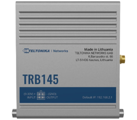
For a detailed look at all the features of this gateway, please visit the manufacturer's website.
Configuration
- First of all, open the case and insert the SIM card. Make sure that the pin-code request is disabled on the SIM card.
- Perform the initial configuration of the gateway according to the Quick Start Guide (supplied with the gateway). After that, you will be able to use the web interface for further configuration and operation of the gateway.
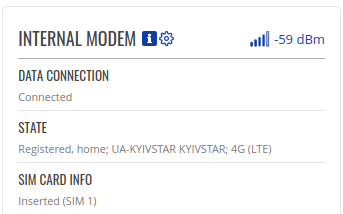
- On the main Status / Overview page, we can check and make sure that the modem has successfully registered in the network:
Sensor connection
The first step is to connect the sensor according to the technical manual:
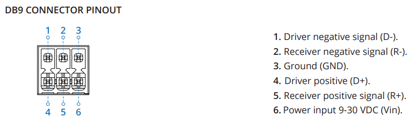
Since the mode will be half-duplex, D- must be connected to R- and D+ connected to R+.
The sensor is connected to an external power supply, and terminals 3 and 6 are not connected. B- of the sensor is connected to pins 1-2 (D- and R-), A+ of the sensor is connected to pins 4-5 (D+ and R+).
Detailed technical information on the sensor connection can be found here.
Modbus Serial Master
Next, we move on to the RS-485 interface and Modbus protocol configuration. In order to receive data from the sensor, our gateway should work as a master and periodically send it to the interface RS-485.
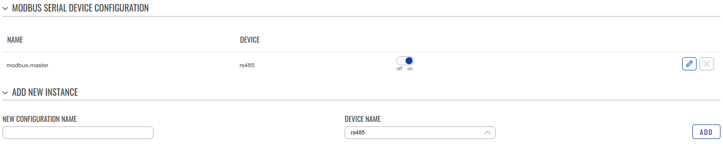
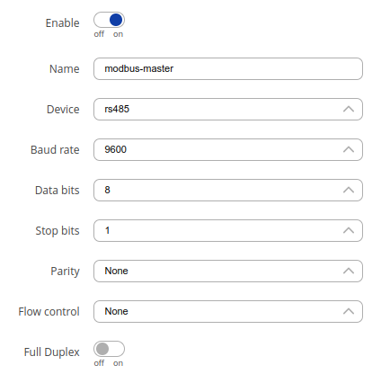
Go to Services / Modbus / Modbus Serial Master (services/modbus/modbus_serial_master):
- Create MODBUS SERIAL DEVICE CONFIGURATION:
- Enter “NEW CONFIGURATION NAME”:

- Click “ADD” and the configuration is added:
- Proceed to the RS-485 parameter setting as specified in the technical manual of the sensor. A detailed description of all the parameters of the gateway can be found here. Screenshot from the manual:

- Click “SAVE & APPLY”.
- Enter “NEW CONFIGURATION NAME”:
- Create MODBUS SLAVE DEVICE CONFIGURATION:
- Enter the name of the new configuration and select MODBUS SERIAL MASTER INSTANCE NAME (modbus-master):
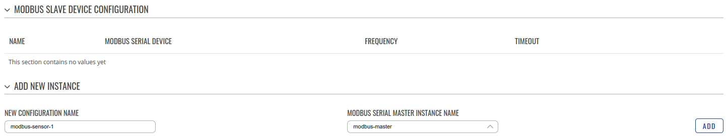
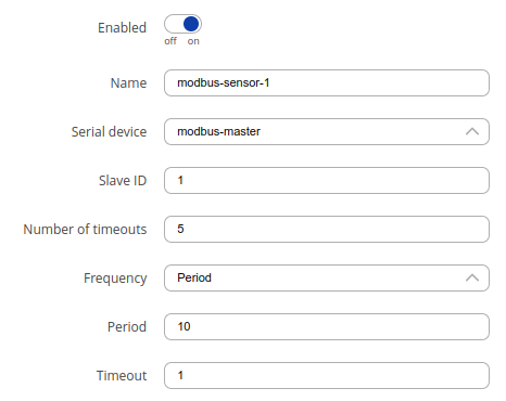
- Cick “ADD”. The slave device configuration window will be opened. Let’s configure it:
- First of all, it’s necessary to specify the slave ID (must be specified in the technical manual of the device). Screenshot from the manual:
-
Set the other parameters:
-
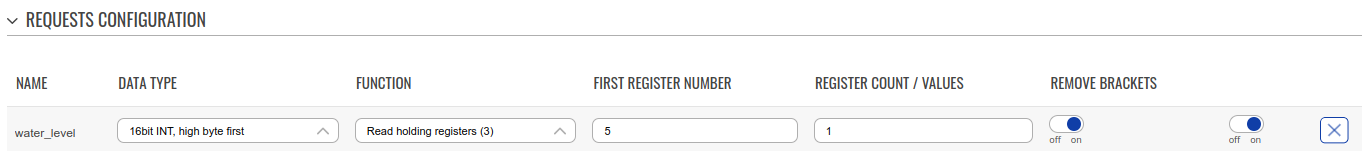
After that, we proceed to the configuration of the registers and the data from which we want to read. In the WS101LL sensor, the data of the register containing the measured value.

-
Enter the name in the “NEW CONFIGURATION NAME” and click the “ADD” button:
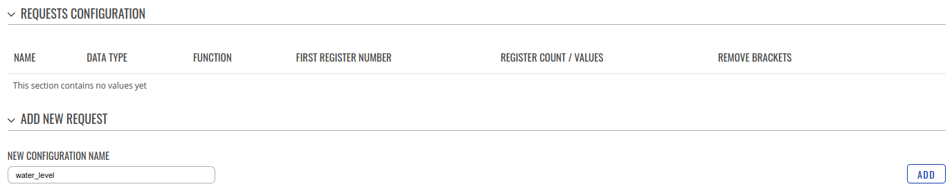
Note: The entered name will be used automatically as a parameter in the JSON that will be sent to the platform. Therefore, it’s necessary that this name adheres to the restrictions. -
Select Data Type - “16bit INT, high byte first” according to the technical manual of the sensor:

(Screenshot from the device's manual) -
Select Function - Read holding registers (3) according to the technical manual:

(Screenshot from the device's manual) - Set the FIRST REGISTER NUMBER to 5, according to the PLC Add column (see the bale from 2.2.3) from the technical manual
-
Set the REGISTER COUNT / VALUES to 1:
If the sensor is connected and powered, you can perform a test reading from the sensor by selecting the desired parameter in the Requests and pressing the “TEST” button: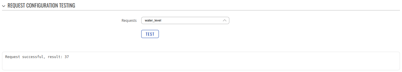
- Click SAVE & APPLY.
- Enter the name of the new configuration and select MODBUS SERIAL MASTER INSTANCE NAME (modbus-master):
Your Modbus configuration is complete.
Setting up the Kaa Cloud account
To connect your device to the platform, we first need to create an account and get a 14 days Free Trial.
Once the Kaa Cloud account is created and you are on the Kaa Cloud Web Dashboard, we need to create an Application (let's call it “Water sensor”), Application Version, and Endpoint.
If you face any issues, please read the Connect your first device tutorial. Also, we recommend reading the Collecting data from a device tutorial. This will provide a better understanding of how the platform accepts data from devices.
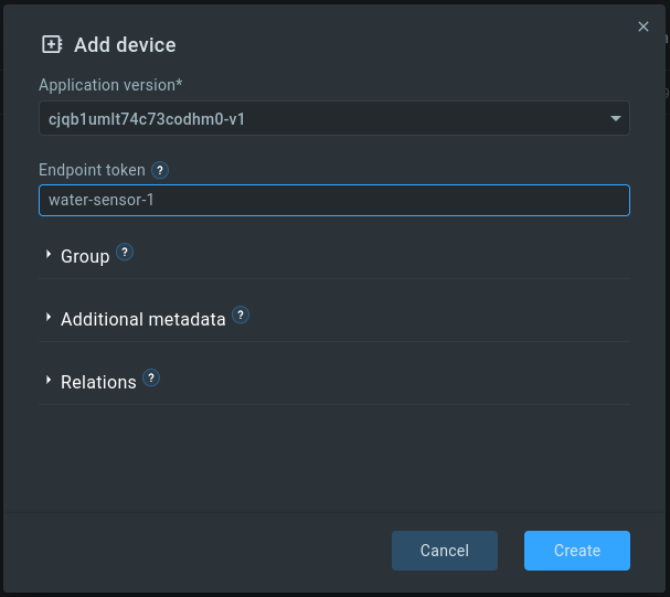
We created an Application named cjqb1umlt74c73codhm0 and created the Endpoint token with water-sensor-1:
Note: Don’t forget to enable the Autoextract option in EPTS settings of your application and select Fallback strategy: server-timestamp (this will allow you to save time-series with the current server time (in case the timestamp parameter is missing in the request):
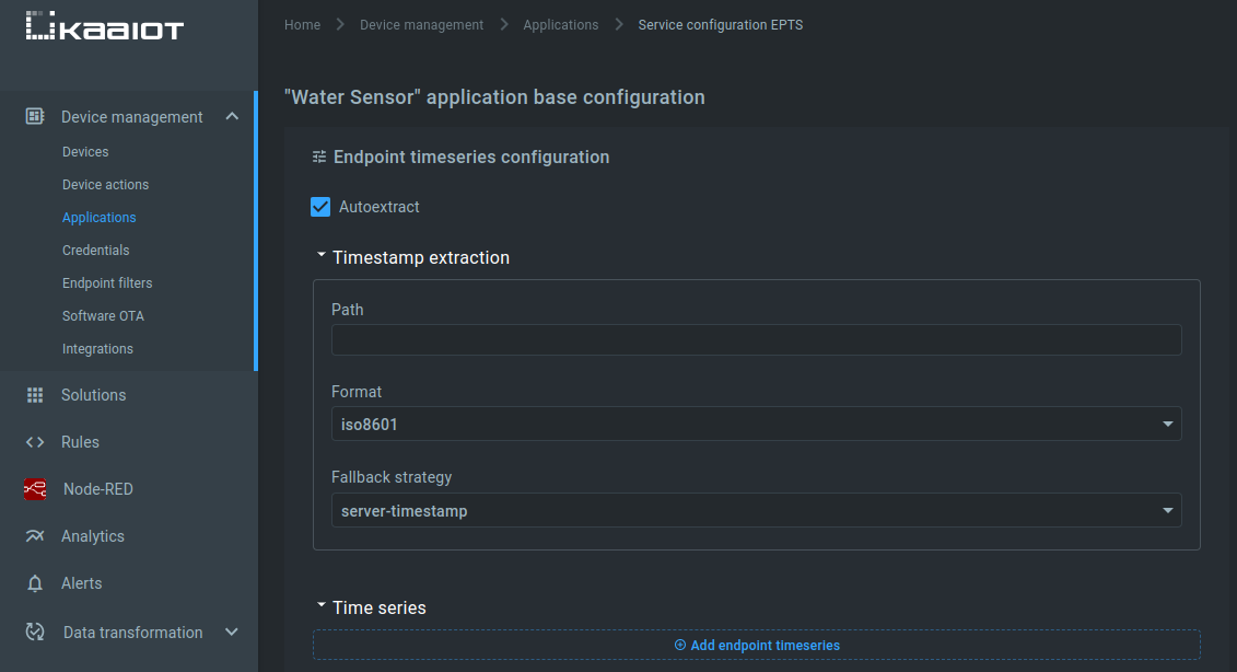
The same settings should be set for the application version.
Data to Server
The next step is to configure the gateway to send data to the Kaa IoT Platform.
Go to Services / Data to Server (services/data_sender) and click the ADD button. Fill in the fields (detailed description of fields):
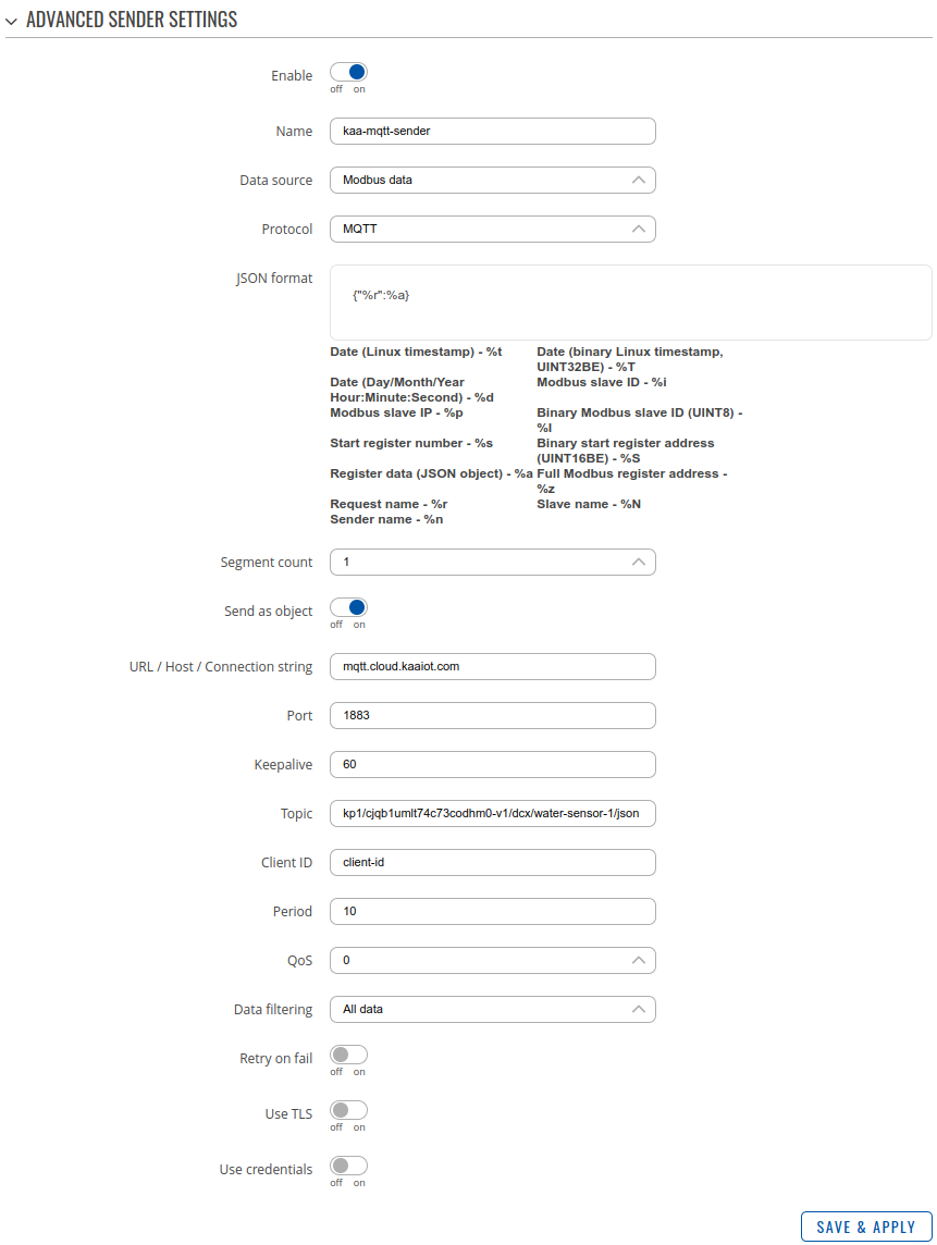
- Name - Name of the data sender. Used for easier data senders management purposes only (optional): enter kaa-mqtt-sender.
- Data Source - Source of the data to be sent to server: Since our sensor uses the Modbus protocol, we’ve chosen the Modbus data.
- Protocol - Protocol used for sending the data to server. In our case, it will be MQTT because this is the main Kaa IoT platform protocol for device connectivity.
- JSON format - Arranges the format of the sent JSON segment. This expression defines what data and under what name will be sent to the platform. In our case, this should be based on Kaa IoT Data Collection RFC. To support our RFC let`s set {"%r":%a} where %r - parameter name from (2.2.4) and %a is a parameter value.
- Segment count - Max segment count in one JSON string sent to server. Select 1 so that each polling of the Modbus slave device is transmitted in a separate JSON packet. This is required for our EPTS (endpoint time series services) configuration in Kaa IoT cloud settings.
- Send as object - When turned on, sends JSON segment as object and not as an array element. In our case, this is what we need because it allows the platform to auto-extract data directly from JSON. Enable this option.
- URL / Host / Connection string - URL of the server. In our case - mqtt.cloud.kaaiot.com. Note: This parameter can be found on the tab Help/Connectivity.
- Port - Port number for connecting to MQTT. Set 1883.
- Keepalive - MQTT Keep-alive period in seconds. Keep the default value.
-
Topic - MQTT topic to be used for publishing the data. Here we have to specify the value of the Kaa IoT platform's MQTT topic. In order to find out what topic we need - go to Help/Connectivity and in the upper right corner, enter the value of our token and application version name:
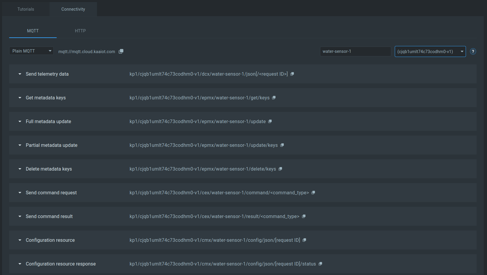
We get the values of the various topics that we can use. In this case, we are interested in the first item Send telemetry data. For now, we ignore [</request ID>].
The topic we should have:
kp1/cjqb1umlt74c73codhm0-v1/dcx/water-sensor-1/json - Client ID - Client ID to send with the data. If empty, a random client ID will be generated. Enter client-1;
- Period - Data sending frequency (in seconds). We read data from the sensor every 10 seconds. That's why we set it to 10 seconds so that it goes straight to the platform.
-
All other fields are left as default.
Our connection to the server has been established:
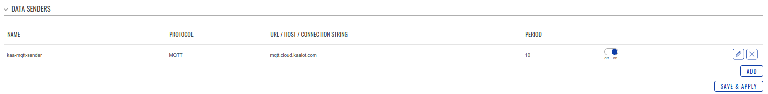
Click SAVE & APPLY.
Now we can go to our Kaa IoT Cloud account in Devices, select our Application, Endpoint, and we can see that the data has started coming in.
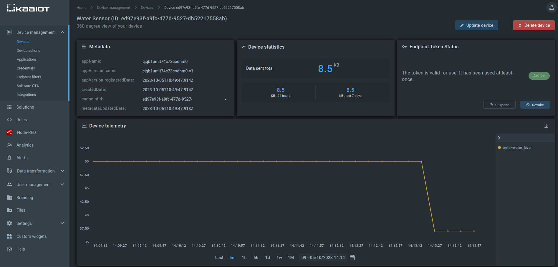
The liquid level sensor with the RS-485 interface and Modbus protocol is connected to the Kaa IoT platform.
Final words
In this tutorial, we've explored how to seamlessly connect your Modbus device to the powerful Kaa IoT platform. With KaaIoT, you gain centralized control, secure data management, real-time monitoring, and the ability to seamlessly integrate with other IoT devices and applications.
Ready to experience the benefits firsthand? Start your journey with KaaIoT today and get a free trial to unlock the full potential of your IoT devices!
Related Stories

KaaIoT and ELSYS join forces to bring robust smart building solutions with real-time climate monitoring.
Exciting news! KaaIoT has teamed up with Roomsys to promote smart building management IoT solutions!

The KaaIoT and Sensative partnership tackles a common challenge: water & oil leaks.

Seeed offers a wide range of IoT hardware products. This article explores how KaaIoT and Seeed are joining...