
How to connect ESP32-CAM to the Kaa IoT platform
In the realm of IoT (Internet of Things), the ability to gather data from IoT devices is essential. However, what if you require more than just numerical readings? What if you want to view real-time video feeds from your devices? This is where network cameras come into play, providing a visual dimension to your IoT projects. However, for those who prefer a hands-on approach and enjoy coding their solutions from scratch, the do-it-yourself (DIY) route beckons.
In this article, we explore the realm of do-it-yourself IoT by discussing how to connect the ESP32-CAM module to the Kaa IoT platform. The ESP32-CAM, with its integrated camera module, offers a wide range of possibilities for streaming live video feeds along with sensor data. Meanwhile, the Kaa IoT platform offers a robust framework for managing and analyzing this data, providing seamless integration for your do-it-yourself (DIY) IoT projects.
Whether you're a hobbyist looking to experiment with DIY IoT or a developer seeking to implement customized solutions, this tutorial will guide you through the process of connecting your ESP32-CAM to the Kaa IoT platform. This will empower you to create innovative and interactive IoT applications. Let's explore and harness the potential of integrating camera capabilities with IoT functionality.
Prerequisites
To continue with this guide we will need the following:
- ESP32-CAM
- Kaa Cloud account
- Arduino IDE
Hardware overview
The heart of the ESP32-CAM is an ESP32-S System-on-Chip (SoC) from Ai-Thinker. Being an SoC, the ESP32-S chip contains an entire computer—the microprocessor, RAM, storage, and peripherals—on a single chip. While the chip’s capabilities are quite impressive, the ESP32-CAM development board adds even more features to the mix. Let’s take a look at each component one by one.
ESP32-S Processor
The ESP32-CAM equips the ESP32-S surface-mount printed circuit board module from Ai-Thinker. It is equivalent to Espressif’s ESP-WROOM-32 module (same form factor and general specifications).
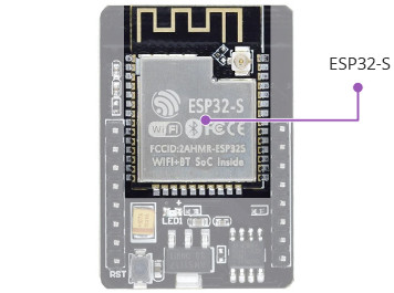
The ESP32-S contains a Tensilica Xtensa® LX6 microprocessor with two 32-bit cores operating at a staggering 240 MHz! This is what makes the ESP32-S suitable for intensive tasks like video processing, facial recognition, and even artificial intelligence.
Memory
Memory is paramount for complex tasks, so the ESP32-S has a full 520 kilobytes of internal RAM, which resides on the same die as the rest of the chip’s components.
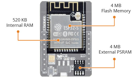
It may be inadequate for RAM-intensive tasks, so ESP32-CAM includes 4 MB of external PSRAM (Pseudo-Static RAM) to expand the memory capacity. This is plenty of RAM, especially for intensive audio or graphics processing.
All these features amount to nothing if you don’t have enough storage for your programs and data. The ESP32-S chip shines here as well, as it contains 4 MB of on-chip flash memory.
Camera
The OV2640 camera sensor on the ESP32-CAM is what sets it apart from other ESP32 development boards and makes it ideal for use in video projects like a video doorbell or nanny cam.
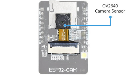
The OV2640 camera has a resolution of 2 megapixels, which translates to a maximum of 1600×1200 pixels, which is sufficient for many surveillance applications.
The ESP32-CAM is compatible with a wide variety of camera sensors.
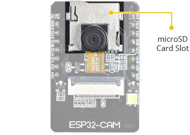
Storage
The addition of a microSD card slot on the ESP32-CAM is a nice bonus. This allows for limitless expansion, making it a great little board for data loggers or image capture.
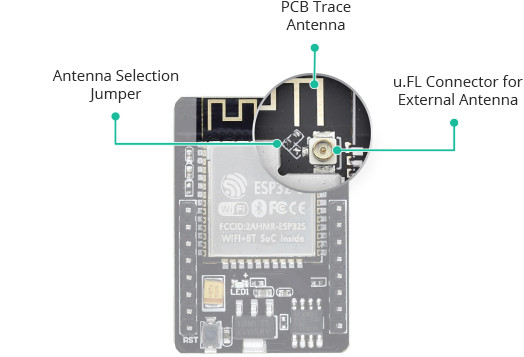
Antenna
The ESP32-CAM comes with an on-board PCB trace antenna as well as a connector for connecting an external antenna. An Antenna Selection jumper (zero-ohm resistor) allows you to choose between the two options.
LEDs
The ESP32-CAM has a white square LED. It is intended to be used as a camera flash, but it can also be used for general illumination.
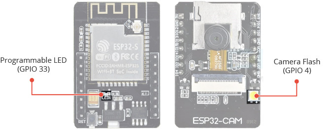
There is a small red LED on the back that can be used as a status indicator. It is user-programmable and connected to GPIO33.
There is a pinout of the module:
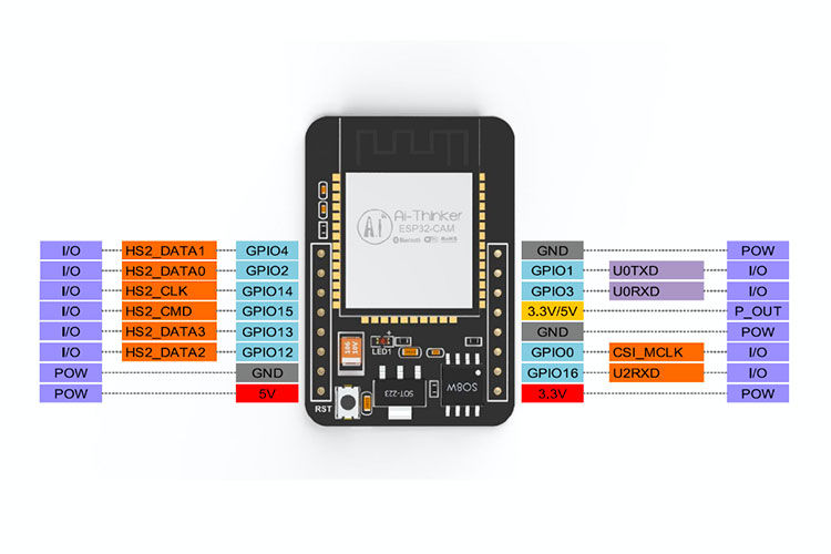
Notes about the power pins. There are two power pins: 5V and 3V3. The ESP32-CAM can be powered via the 3.3V or 5V pins. Since many users have reported problems when powering the device with 3.3V, it is advised that the ESP32-CAM always be powered via the 5V pin. The VCC pin normally outputs 3.3V from the on-board voltage regulator. It can, however, be configured to output 5V by using the Zero-ohm link near the VCC pin.
The schematic of the module can be found by link.
Technical Specifications
To summarize, the ESP32-CAM has the following specifications.
- Processors:
- CPU: Xtensa dual-core 32-bit LX6 microprocessor, operating at 240 MHz and performing at up to 600 DMIPS
- Ultra-low power (ULP) co-processor
- Memory:
- 520 KB SRAM
- 520 KB SRAM
- 4MB internal flash memory
- Wireless connectivity:
- Wi-Fi: 802.11 b/g/n
- Bluetooth: v4.2 BR/EDR and BLE (shares the radio with Wi-Fi)
- Camera:
- 2 Megapixel OV2640 sensor
- Array size UXGA 1622×1200
- Output formats include YUV422, YUV420, RGB565, RGB555 and 8-bit compressed data
- Image transfer rate of 15 to 60 fps
- Built-in flash LED
- Support many camera sensors
- Supports microSD card
- Security:
- IEEE 802.11 standard security features all supported, including WFA, WPA/WPA2 and WAPI
- Secure boot
- Flash encryption
- 1024-bit OTP, up to 768-bit for customers
- Cryptographic hardware acceleration: AES, SHA-2, RSA, elliptic curve cryptography (ECC), random number generator (RNG)
- Power management:
- Internal low-dropout regulator
- Individual power domain for RTC
- 5μA deep sleep current
- Wake up from GPIO interrupt, timer, ADC measurements, capacitive touch sensor interrupt
Module programming
Now that we have explored the hardware capabilities of the ESP32 module, it's time to roll up our sleeves and dive into the exciting world of coding! When it comes to developing software for the ESP32, there are two main approaches: using the ESP-IDF (Espressif IoT Development Framework) or the Arduino framework. In this tutorial, we'll choose the Arduino framework because of its simplicity and ease of use.
Before we begin coding, it is assumed that you have already installed the Arduino IDE. If not, there are plenty of resources available online to guide you through the installation process. Once the Arduino IDE is up and running, our first step is to configure it to work seamlessly with ESP32-based modules.
In this section, we will guide you through the process of adding the required Board Manager for the ESP32, ensuring that our Arduino IDE is ready to handle ESP32 development tasks. Let's prepare our Arduino IDE for action!
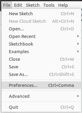
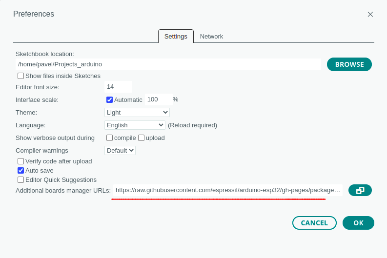
Let's go to the File > Preferences
In the “Additional Board Manager URLs” field we have to add the following link:
https://raw.githubusercontent.com/espressif/arduino-esp32/gh-pages/package_esp32_index.json
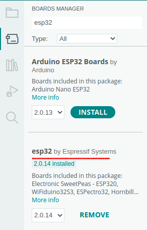
With our Arduino IDE open, the next step is locating the ESP32 in the Boards Manager, conveniently located in the left menu. Here, we'll install the ESP32 board package provided by Espressif Systems. This package equips our Arduino IDE with the necessary tools and configurations to seamlessly develop and deploy code for ESP32-based projects.
Let's navigate to the “Boards Manager” and install the “esp32 by Espressif Systems” package, ensuring that our development environment is fully equipped to tackle the challenges and opportunities presented by the ESP32 module.
Now that we've successfully installed the esp32 by Espressif Systems package via the Boards Manager, it's time to connect our ESP32 module to the PC for programming. However, it's worth noting that the ESP32 module itself does not have a built-in USB port. Fear not, as there are two common methods for connecting and programming the module: using a USB-to-serial adapter or an ESP32-CAM-MB programmer adapter.
These options offer flexibility depending on your available hardware and preferences. Whether you choose the simplicity of the USB-to-serial adapter or the convenience of the ESP32-CAM-MB programmer adapter, both methods will facilitate seamless communication between your ESP32 module and the Arduino IDE, enabling effortless programming and development.
Let's explore each method in detail to ensure that you have the knowledge and tools necessary to proceed with confidence in your ESP32 development endeavors.
Using USB-to-serial adapter
We can use an FTDI adapter or other USB-to-serial adapters (for example based on CP2102, PL2303, etc.).
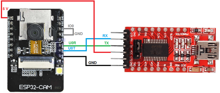
Note: Make sure the jumper is set to 5V.
Many FTDI programmers come equipped with a jumper that allows you to select between 3.3V and 5V power levels. Since we're powering the ESP32-CAM with 5V, make sure that this jumper is set to 5V to avoid any potential issues.
Remember that when programming the ESP32-CAM, the GPIO 0 pin needs to be connected to Ground. However, once the programming process is complete, you must disconnect this connection.
You will need to establish this connection every time you want to upload a new sketch to the ESP32-CAM.
Additionally, if you are using a UNIX-based operating system, such as Ubuntu, it is important to grant read-write privileges to the USB port. You can achieve this by executing the command 'sudo chmod a+rw /dev/ttyUSB0' in the terminal.
Using the ESP32-CAM-MB Adapter (recommended)
Using the FTDI Adapter for programming the ESP32-CAM can be a bit cumbersome. That's why many vendors now offer the ESP32-CAM board bundled with a convenient add-on daughterboard known as the ESP32-CAM-MB.
With the ESP32-CAM stacked onto the daughterboard, simply connect a micro USB cable, and with a click of the Upload button, you're ready to program your board. It's as straightforward as that.
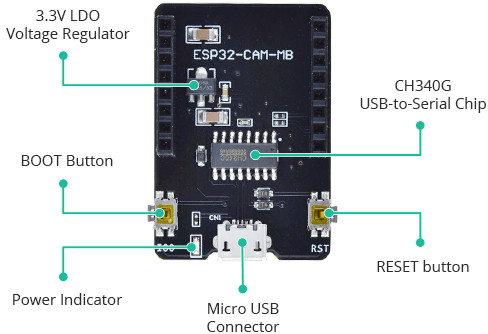
One of the key features of this board is the CH340G USB-to-Serial converter, which facilitates seamless data translation between your computer and the ESP32-CAM. Additionally, you'll find a RESET button, a BOOT button, a power indicator LED, and a voltage regulator onboard, ensuring that the ESP32-CAM receives ample power for optimal performance.
Arduino IDE configuration
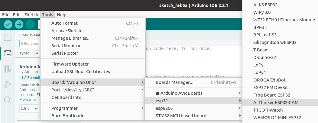
After connecting the module let's go to the Arduino IDE, create a new sketch, and select the board AI-Thinker ESP32-CAM
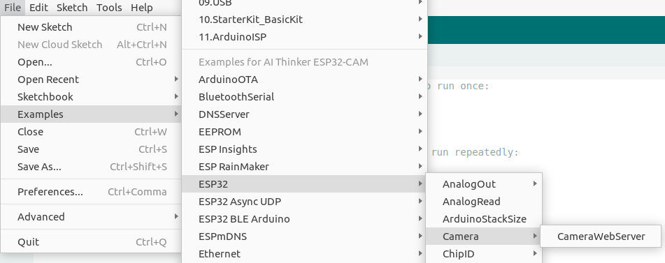
Moving on to the examples, we can easily find a ready-made example for working with the camera module
To make this example work on our ESP32-CAM module we have to choose CAMERA_MODEL_AI_THINKER and fill in the WiFi credentials:
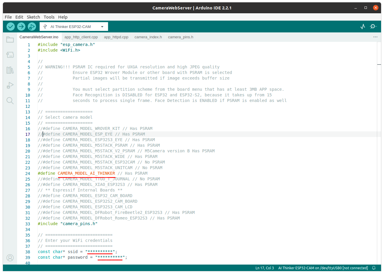
Once we compile and upload the firmware to the module, the ESP32-CAM's built-in web server will automatically run. The URL to access this web server will be displayed in the Serial Monitor window. By logging into this web server, we gain access to the video stream from the camera and can adjust various settings.
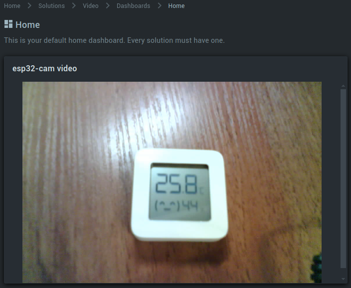
Integrating live video streaming from ESP32-CAM into the Kaa IoT dashboard.
While the described functionality may be sufficient for some applications, our goal is to stream the video directly to the Kaa Cloud dashboard widget.
Imagine a scenario with a dashboard displaying measurements from various sensors in a server room. Suddenly, we notice a spike in temperature readings or receive an alert from the smoke sensor. In such situations, we want the ability to instantly access live video from the server room directly on the Kaa Cloud dashboard, providing us with real-time insights into the situation at hand.
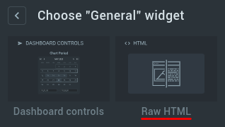
For this situation, we can use the Raw HTML widget and set the video stream URL inside this widget.
Now, the question arises: how can we obtain a video stream?
The existing CameraWebServer example operates as follows: it periodically captures an image from the camera, converts it to JPG format, and subsequently transmits it via an open web socket, resulting in a video stream in MJPEG format.
However, we've modified the logic of the code concerning how and where the processed image is sent. Depending on the selected resolution, the size of the image may vary. Presently, the processed image is fragmented and transmitted via UDP to the server.
To facilitate this process, we'll utilize the Node-RED service as a node for receiving data from cameras and relaying it for utilization by the Raw HTML widget. This setup ensures seamless integration of the video stream into our IoT dashboard.
Let’s look at the Node-RED flow:
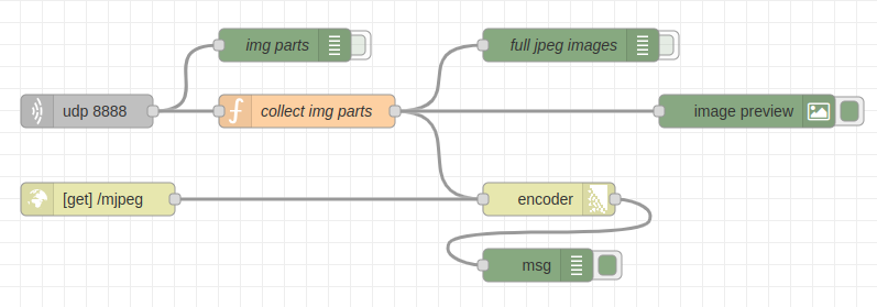
At the input, we have a UDP server that receives data from the camera. After this, we need to collect fragments of pictures into whole images. This is what the “collect img parts” node does.
To preview the collected MJPEG stream we use the “image preview” node.
To generate a video stream for display, we use nodes “[get] /mjpeg” & “encoder”.
Let's deploy flow in Node-RED and connect the camera.
Sources for the camera can be downloaded from the link
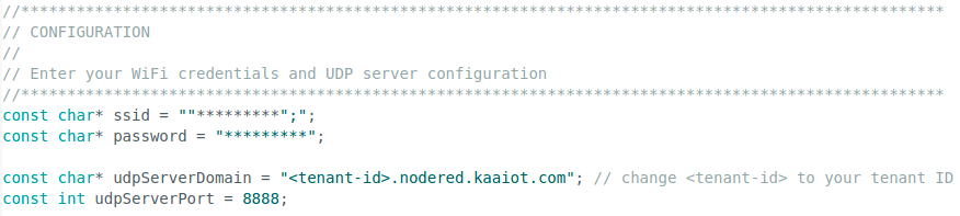
Unlike the original example, we're required to input not only the WiFi access credentials but also provide the URL and port number of our Node-RED flow.
As a reminder, the Node-RED URL takes the form: <tenant-id>.nodered.kaaiot.com. This information ensures seamless communication between our ESP32-CAM module and the Node-RED service hosted on the Kaa IoT platform.
Once we've entered the necessary data, we proceed to compile and flash our module.
Upon launching the module in the Serial Monitor window, we'll observe that the WiFi connection has been established, and we'll be presented with the IP address of our Node-RED server. Similar to the original example, we retain the option to navigate to the camera page using the provided IP address. Here, we can manage settings such as backlight control, resolution selection, and more.
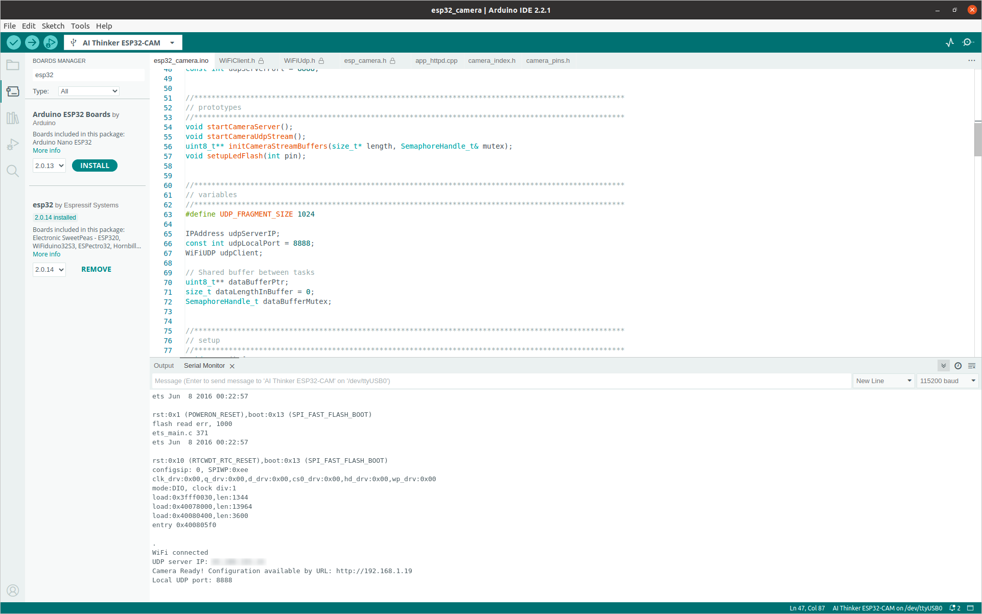
Additionally, to see what size of the file we are currently sending to the Serial monitor, for debugging purposes, the size of every 20th file sent is displayed. The frequency of sending images depends on the selected resolution.
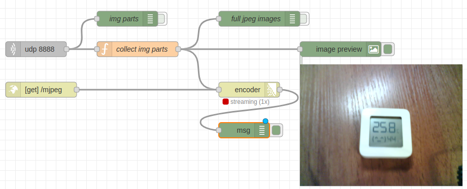
Upon returning to Node-RED, we'll be able to observe the preview of the video stream.
Now, we'll set up the RawHTML widget to display the video stream. Simply follow these steps:
- Navigate to the RawHTML widget configuration.
- Paste the following code snippet into the HTML context field
    <div style='color: rgb(250, 174, 66);justify-content: center;align-items: center;display: flex;height: 100%'>
        <div style="margin-bottom: 10px;">
            <img src="https://<tenant-id>.nodered.kaaiot.com:1880/mjpeg" width="600px">
        </div>
    </div>
! Don’t forget to set your tenant ID instead <tenant-id>
Once the widget configuration is saved, you'll notice that the video stream is now visible on our dashboard:
Source code
[
    {
        "id": "65ee1c6dac5ab593",
        "type": "tab",
        "label": "video",
        "disabled": false,
        "info": "",
        "env": []
    },
    {
        "id": "100b32804cc3fe3e",
        "type": "udp in",
        "z": "65ee1c6dac5ab593",
        "name": "",
        "iface": "",
        "port": "8888",
        "ipv": "udp4",
        "multicast": "false",
        "group": "",
        "datatype": "buffer",
        "x": 100,
        "y": 200,
        "wires": [
            [
                "427f9cac2265e4b0",
                "772c0eb8d4fe6ecd"
            ]
        ]
    },
    {
        "id": "427f9cac2265e4b0",
        "type": "debug",
        "z": "65ee1c6dac5ab593",
        "name": "img parts",
        "active": false,
        "tosidebar": true,
        "console": false,
        "tostatus": false,
        "complete": "true",
        "targetType": "full",
        "statusVal": "",
        "statusType": "auto",
        "x": 280,
        "y": 140,
        "wires": []
    },
    {
        "id": "772c0eb8d4fe6ecd",
        "type": "function",
        "z": "65ee1c6dac5ab593",
        "name": "collect img parts",
        "func": "const FRAGMENT_SIZE = 1024;\n\nvar length = msg.payload.length;\n\n// push data to buffer\nvar buffer = flow.get(\"IMG_BUFFER\");\nif (buffer == null) {\n    buffer = [];\n}\nfor(var i=0; i<length; i++) {\n    buffer.push(msg.payload[i]);\n}\n\nif (length == FRAGMENT_SIZE) {\n    flow.set(\"IMG_BUFFER\", buffer);\n    return;\n}\n\n// last packet    \nflow.set(\"IMG_BUFFER\", []);\nmsg.payload = Buffer.from(buffer);\n\nreturn msg;",
        "outputs": 1,
        "noerr": 0,
        "initialize": "",
        "finalize": "",
        "libs": [],
        "x": 300,
        "y": 200,
        "wires": [
            [
                "74436ad111e2198a",
                "bc51052fd5b98b97",
                "6f27b9f10517d26e"
            ]
        ]
    },
    {
        "id": "74436ad111e2198a",
        "type": "debug",
        "z": "65ee1c6dac5ab593",
        "name": "full jpeg images",
        "active": false,
        "tosidebar": true,
        "console": false,
        "tostatus": false,
        "complete": "true",
        "targetType": "full",
        "statusVal": "",
        "statusType": "auto",
        "x": 540,
        "y": 140,
        "wires": []
    },
    {
        "id": "bc51052fd5b98b97",
        "type": "multipart-encoder",
        "z": "65ee1c6dac5ab593",
        "name": "",
        "statusCode": "",
        "ignoreMessages": true,
        "outputOneNew": false,
        "outputIfSingle": false,
        "outputIfAll": false,
        "globalHeaders": {
            "Content-Type": "multipart/x-mixed-replace;boundary=--myboundary",
            "Connection": "keep-alive",
            "Expires": "Fri, 01 Jan 2026 00:00:00 GMT",
            "Cache-Control": "no-cache, no-store, max-age=0, must-revalidate",
            "Pragma": "no-cache"
        },
        "partHeaders": {
            "Content-Type": "image/jpeg"
        },
        "destination": "all",
        "highWaterMark": 16384,
        "x": 520,
        "y": 280,
        "wires": [
            [
                "59cf20db819c888b"
            ]
        ]
    },
    {
        "id": "cc6f9fc57e49a6c4",
        "type": "http in",
        "z": "65ee1c6dac5ab593",
        "name": "",
        "url": "/mjpeg",
        "method": "get",
        "upload": false,
        "swaggerDoc": "",
        "x": 110,
        "y": 280,
        "wires": [
            [
                "bc51052fd5b98b97"
            ]
        ]
    },
    {
        "id": "6f27b9f10517d26e",
        "type": "image",
        "z": "65ee1c6dac5ab593",
        "name": "",
        "width": "320",
        "data": "payload",
        "dataType": "msg",
        "thumbnail": false,
        "active": true,
        "pass": false,
        "outputs": 0,
        "x": 700,
        "y": 200,
        "wires": []
    },
    {
        "id": "59cf20db819c888b",
        "type": "debug",
        "z": "65ee1c6dac5ab593",
        "name": "",
        "active": true,
        "tosidebar": true,
        "console": false,
        "tostatus": false,
        "complete": "true",
        "targetType": "full",
        "statusVal": "",
        "statusType": "auto",
        "x": 510,
        "y": 360,
        "wires": []
    }
]
Conclusion
In conclusion, we've embarked on an exciting journey to connect the ESP32-CAM module to the Kaa IoT platform and adding live video streaming to your IoT dashboard, enriching our IoT projects with live video streaming capabilities. From configuring the Arduino IDE and setting up the ESP32 board package to modifying code logic and integrating with Node-RED, we've explored various steps to achieve our goal.
Through this tutorial, we've learned how to leverage the ESP32-CAM's camera module and the Kaa IoT platform's features to create dynamic and interactive IoT applications. By streaming live video to our dashboard, we've empowered ourselves with real-time insights and enhanced monitoring capabilities.
As we conclude our tutorial, we encourage you to continue exploring the vast possibilities offered by the Kaa IoT platform. Whether you're monitoring server rooms, securing premises, or innovating in any other domain, the combination of camera functionality and IoT connectivity opens doors to endless possibilities. Thank you for joining us on this journey, and happy coding!
Related Stories
KaaIoT and ELSYS join forces to bring robust smart building solutions with real-time climate monitoring.
Exciting news! KaaIoT has teamed up with Roomsys to promote smart building management IoT solutions!
The KaaIoT and Sensative partnership tackles a common challenge: water & oil leaks.
Seeed offers a wide range of IoT hardware products. This article explores how KaaIoT and Seeed are joining...